 The Pacific War Online Encyclopedia
|
| Previous: Gunn, Paul | Table of Contents | Next: Guntakal |
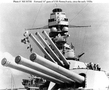
Naval Historical Center #50758
Naval guns remained an important category of weapon in spite of the ascendancy of aircraft. They served in three main roles.
Antiship. The heaviest guns on a naval vessel were usually intended for the antiship role. Battleship guns could hurl shells that were 12" to 16" (30 to 40 cm) in diameter and weighed a good fraction of a ton to distances of up to 26 miles (42 km). Cruiser guns were much smaller in caliber (6" or 8" or 15 to 20 cm), still comparable with the heaviest corps artillery. Destroyer guns were comparable to divisional artillery at 4" to 5" (10 to 13 cm), while minor warships typically carried 3" (76mm) main armament.
Antiship rounds were classified as armor piercing or high explosive. Armor piercing (AP) shells were made of hardened chrome steel, usually with a softer nose cap (APC), and carried a small bursting charge with a delayed fuse. The shell was carefully heat-treated to give maximum hardness to the tip of the shell while letting the rest of the shell body retain its toughness. Armor piercing shells were designed to penetrate armor plate through sheer brute force, with the fuse setting off the bursting charge twenty or thirty milliseconds after hitting substantial armor plating. This gave the shell time to pass into the interior of the ship where its fragments would do the most damage. However, an armor piercing shell hitting an unarmored target might well pass entirely through the target without every hitting anything substantial enough to activate the fuse. The soft cap of an APC shell improved penetration of face-hardened armor by protecting the hard tip of the shell from shattering against the armor. However, in the continuing race between arms and armor, a number of naval powers adopted protection systems featuring internal armor belts with outboard shells designed to strip the soft cap off of APC shells before they hit the main armor belt.
The Japanese came up with an interesting variant
of the armor piercing shell, which was called the Type 91 AP Shell or
diving shell. This shell was designed such that if it fell slightly
short, it would continue through the water to hit the hull of the
target ship well below the waterline, where the armor was light or
nonexistent. This had the potential to cause extensive flooding. The
Type 91 had a blunt nose with a thin aerodynamic cap that shattered on
entering the water. American ordnance experts deduced the properties of
the Type 91 from examining the damage from its one success, the
near-destruction of Boise. They noted that it had
poor penetration against heavier armor, and no attempt was made by the Americans to
duplicate it. However, it seems likely that intelligence on the Type 91 figured in the British development of the "Shark" shell in 1944, which was a 4" (102mm) antisubmarine shell used in the Atlantic.
High explosive (HE) shells were
intended for
use against unarmored targets and so did not require as stout a shell body as an armor piercing shell.
Whereas an armor
piercing shell carried perhaps 5% of its weight as high explosive, a
high
explosive shell carried about 20% of its weight as high explosive. High
explosive shells were equipped with fuses that were activated on
hitting quite thin plating, although naval high explosive shells, like
armor piercing shells, typically set off the explosive charge some
milliseconds after being activated to allow the shell to penetrate.
The effectiveness of various large-caliber armor piercing rounds is summarized in the following table, which gives the maximum thickness of Krupp cemented armor penetrated by the round at a given range (Friedman 1985):
| Shell\Range in yards |
Muzzle Velocity |
6500 |
8000 |
10,000 |
12,000 |
14,000 |
16,000 |
20,000 |
22,000 |
|---|---|---|---|---|---|---|---|---|---|
| 12" (305mm) |
2900 fps (884 m/s) |
18.7" (475mm) |
17.3" (439mm) |
15.6" (396mm) |
14.1" (358mm) |
12.8" (325mm) |
11.7" (297mm) |
10.0" (254mm) |
9.5" (241mm) |
| 14" (356mm) |
2600 fps (792 m/s) |
19.0" (483mm) |
17.6" (447mm) |
15.9" (404mm) |
14.4" (366mm) |
13.2" (335mm) |
12.1" (307mm) |
10.7" (272mm) |
|
| 16" (406mm) |
2400 fps (732 m/s) | 20.0" (508mm) |
18.5" (470mm) |
17.2" (437mm) |
16.0" (406mm) |
13.7" (348mm) |
|||
| 16" (406mm) |
2500 fps (762 m/s) |
19.6" (498mm) |
18.2" (462mm) |
15.9" (404mm) |
13.8" (351mm) |
These figures are for penetration of a vertical armor belt. Penetration of horizontal armor was much less at close range, due to the shallow angle of impact, so that a 14" shell just failed to penetrate simulated 5" STS deck armor in tests carried out by the U.S. Navy in 1917. Penetration of horizontal armor actually increased at longer range, due to the steeper angle of descent, so that a 16" shell penetrated just 2.65" (67mm) of horizontal STS at 18,000 yards but 4.5" (114mm) at 30,000 yards. Deck hits were also more likely than belt hits at long range. While the split was roughly 50/50 between deck and belt hits at 15,000 yards for a 16" shell, the ratio increased to 80/20 at 30,000 yards.
To penetrate the target, it was first necessary to hit the target. This was a difficult problem for long-range gunnery against moving ships, requiring the gun to place the shell where the ship would be when the shell arrived. The U.S. Navy used various models of the the Ford Rangekeeper from 1916 on to compute the correct firing angle and elevation. This highly classified technology permitted the rapid development of U.S. long-range gunnery following the First World War. Other powers had their own equally closely guarded fire control systems.
The damage done by a shell penetrating the armored citadel of a warship could range from minor to catastrophic. A shell hitting a magazine could cause a magazine explosion that would sink the ship immediately. In a series of tests in 1937, the German Navy set off various sizes of shells in the engineering spaces of an obsolete battleship. These tests showed that an 11" (28cm) shell would put the engine room out of commission by rupturing steam pipes, forcing its evacuation, but the damage could be repaired in less than six months. However, a 15" (38cm) shell would completely destroy the boilers or engines, requiring complete new equipment whose installation would take well over six months.
The U.S. Naval War College came up with two models for damage to battleships from penetrating hits. The deterministic model assumed that damage was cumulative, so that a battleship was crippled once it had suffered about nine penetrating 14" shell hits and would sink after suffering about 18 penetrating 14" shell hits. The stochastic model, which better matched combat experience, assumed that penetrating hits would have little effect unless they did catastrophic damage, such as by hitting a magazine or engine room. Engine rooms constituted about 20% of a ship's citadel, so a penetrating hit had a 20% chance of knocking out an engine room. Magazines constituted about 23% of a ship's citadel, so there was about a 23% chance of a penetrating hit destroying the ship outright through a magazine explosion. The stochastic model thus predicted more ship losses to penetrating hits than the deterministic model.
Determining whether a shell will penetrate a given armor
protection system is not a straightforward exercise. Penetration
depends not only on what kind of shell is being fired and where it
hits, but also on the angle and range of the gun relative to the
target. A shell passing through the outer shell or superstructure of a
ship might be stripped of its soft cap or made to tumble, reducing
penetration when it finally hits substantial armor. A shell that does
not penetrate outright might still produce spall, knocking loose a plug
of armor (especially when hitting face-hardened armor) that could cause considerable damage to the interior of the ship.
Okun (2003) has even analyzed a scenario in which increasing the
thickness of a bomb deck increased the likelihood of penetration, by
changing the trajectory of a shell such that it hits the main armor
deck underneath at a steeper angle. Finally, even a non-penetrating hit
will do substantial damage. While this will usually be to nonessential
compartments of the ship, a lucky hit could destroy fire control
elements high in the superstructure that could not be given anything
heavier than splinter protection.
Shore bombardment. Naval guns supplied heavy firepower for a landing force while it was unloading its own artillery. Naval guns were also occasionally turned against shore installations during raids against enemy coasts. Most admirals of the Second World War were hesitant to order their ships to engage in a duel with coastal artillery ("A ship's a fool to fight a fort"), but the Americans became increasingly proficient at destroying fortifications on landing beaches, bringing their ships in very close to shore to improve accuracy. A 16" (406mm) armor-piercing shell from a battleship could penetrate 30' (9 m) of reinforced concrete. Even so, shore bombardments often proved inadequate to protect the landings, as at Iwo Jima.
American naval gunfire in the Pacific was noted for its
accuracy. By the time of the Saipan invasion, naval gunnery was precise
enough to bring down fire as close as 100m to friendly troops, which
was vital for breaking up Japanese night attacks. However, the guns
were as likely to fire illuminating rounds to reveal targets to the
troops ashore as to fire high explosive shells.
Antiaircraft. As the war progressed,
both the Allied
and Japanese navies mounted
every-increasing numbers of
antiaircraft guns on their
naval vessels. These were specialized enough that they are described in their own article.
A gun is essentially a hollow metal tube, closed at one end, which is loaded with a primer, a propellant
charge, and a projectile. The primer contains a tiny charge of a
sensitive explosive, which detonates when crushed by a firing pin or
heated electrically.
The detonation of the primer ignites the propellant charge, which burns
extremely rapidly to produce white-hot gas at enormous pressure. The
barrel must be sufficiently strong to withstand this pressure, which
forces the projectile out of the barrel at high velocity. Constructing a
large caliber gun barrel with the necessary strength is a significant
engineering challenge.
The guns of the Second World War were either of monoblock,
wire-wrapped,
or built-up construction. Monoblock guns were simplest, with a barrel
composed of a single homogeneous metal tube (or, more typically, a
homogeneous metal tube with a thin liner). However, ordinary monoblock
construction was limited to guns of perhaps 6" (15 cm) bore or less.
For larger guns, it was not possible to achieve the necessary chamber
pressures with ordinary monoblock construction, because even the strongest metal
alloys lacked the necessary strength.
Metal gives slightly under pressure, a phenomenon known as
elastic yield. When the pressure is relieved, the metal returns to its
original shape. However, if the pressure reaches the elastic limit of
the particular metal alloy, the metal begins to deform permanently.
This deformation also embrittles the metal, so that metal subject to
great pressure will first deform and then crack. Thus, a gun barrel
could not be subject to pressure beyond its elastic limit, or the gun
would eventually explode when fired.
A thicker barrel spreads the strain from the chamber pressure over a greater area of metal, thus helping keep the metal from reaching its elastic limit. However, this only works up to a point. Because the stress from firing the gun moves through the barrel no faster than the speed of sound, a very thick barrel will reach the elastic limit on its inner surface before the outer part of the barrel has had time to take up any of the stress. The rule of thumb was that a monoblock barrel could not usefully be thicker than half a caliber; that is, a 6" gun could not usefully have a barrel wall thicker than about 3". This was just adequate for a gun of 6" caliber, but inadequate at higher calibers.
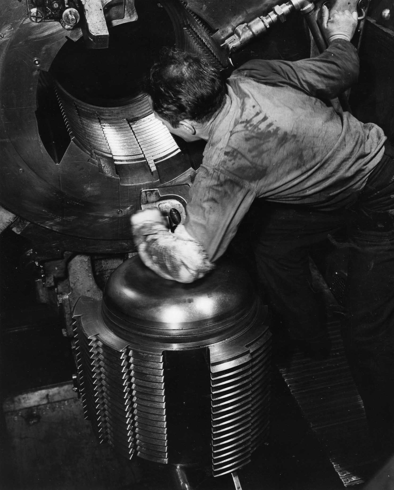
The solution was built-up construction, in which the barrel was composed of concentric homogeneous metal cylinders. At a minimum, the gun had an inner liner and an outer jacket. The jacket was heated to moderately high temperature (200 C or 400 F) so that it expanded sufficiently to allow the cold liner to be inserted within the jacket. When the jacket cooled, it compressed the liner. This process could be repeated to build up a barrel from several layers, as was necessary for the largest caliber guns. Ideally, the liner was compressed to just short of its elastic limit. When the gun was fired, the chamber pressure first took the liner out of compression, then put it into tension, doubling the effective elastic limit of the liner and thereby doubling the maximum safe chamber pressure.
Because the greatest pressure was produced at the breech end of the gun, the muzzle end did not need to be nearly as strong as the breech. Thus, the outer jackets often did not reach all the way to the muzzle, producing a characteristic "stepped" appearance to large-caliber built-up guns.
By the time of the Pacific War, naval guns with bores
between 3" (75mm) and 5" (120mm) bore diameter were typically of
monoblock construction, but used autofrettage (known as radial expansion
in the U.S. Navy) to reduce weight while retaining strength. The
interior of the barrel was hydraulically loaded to a pressure
considerably greater than the normal chamber pressure for firing. When
this was done in a carefully controlled manner, the interior of the
barrel experienced elastic yield without cracking or excessive work
hardening. When the pressure was removed, the outer part of the barrel
was left in tension and the inner part in compression, just as with a
built-up gun. However, the compression varied smoothly through a single
solid tube rather than stepwise in a series of concentric tubes. This
was actually superior to build-up construction, but autofrettage was
impractical for guns of about 6" (150mm) bore or larger because of the
difficulty of forging a single tube of sufficient thickness.
Wire-wrapped construction was an obsolescent technique by the time of the Pacific War, which had been developed and then abandoned by the British as inferior to the best built-up construction. However, the 18" (46 cm) guns on the Yamatos were built using wire-wrapped construction because of the limitations of Japanese metallurgy. A wire-wrapped gun consisted, at a minimum, of a liner surrounded by very tightly wound high-tensile steel wire, which was in turn surrounded by a jacket. The wire was usually rectangular rather than circular in cross-section, so the windings fit tightly together. The wire wrappings gave the barrel great strength against the hoop stresses produced by high chamber pressure, but did not strengthen the gun longitudinally, so that wire-wrapped guns tended to suffer from excessive barrel droop.
U.S. Navy. Via NavSource.org
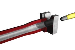
The breech of a gun was closed by a breech block that had
to be able to withstand the chamber pressure during firing while being
easily opened for reloading. For smaller caliber guns using fixed or semifixed
ammunition, the cartridge case provided a tight seal, and a sliding
block could be used to close the breech. This was a solid metal block
held in strong metal jaws that slid vertically or horizontally across
the breech of the barrel.
Almost all large-caliber guns used a Welin
block, a kind of interrupted-thread block. The block and breech were
both threaded, but in staggered segments that allowed the block to be
fully inserted into the breech in a single motion. A partial turn of
the block then engaged the threads to close the breech. However, the
absence of a cartridge meant that another mechanism had to be provided
to provide a gas-tight seal. This seal normally took the form of a De
Bange gas check. This consisted of a metal "mushroom" at the front of
the breech block that was backed by a slightly elastic gas-check pad
made of asbestos and tallow. When the gun was fired, the chamber
pressure pushed the mushroom back into the gas-check pad, forcing the
pad to expand radially and make a tight seal against a gas-check seat at
the rear of the barrel.
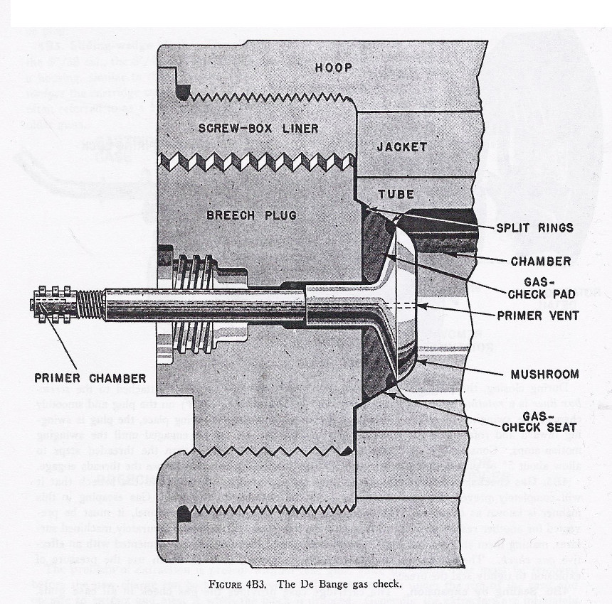
NAVPERS 16116. Click to enlarge.
As important as the gun itself was its mounting. The gun
mounting had to be capable of sufficiently rapid changes in traverse
and elevation to track its target, and traverse and elevation had to be
accurate enough for good fire control. Rapid traverse was a
particularly important feature of antiaircraft guns, which were
tracking particularly fast-moving targets. The gun mounting also had to
be able to absorb the recoil of the gun when it was fired. The basic
laws of physics tell us that the momentum imparted to the projectile
must be matched by an equal momentum imparted to the gun barrel. The
barrel
had to be brought to a halt within a manageable recoil
distance, but slowly enough to minimize the force required to damp the
recoil. The usual recoil absorbers in the gun mountings of
the Pacific War resembled large automobile shock absorbers, using a
combination of compressed air and hydraulic fluid.
Fire control. Guns can destroy only what they can hit. The problem of aiming a gun to hit a distant moving target proved more difficult for for naval engineers to solve than the problem of constructing a gun capable of throwing shells to great distances. Although gunnery improved tremendously from the start of the 20th century to the beginning of the Pacific War, gun accuracy remained only fair even under the best of conditions. Morison (1950) reports that, during the night action at Empress Augusta Bay, the American force fired 4591 6" shells and scored perhaps 20 hits. This hit probability of 0.4% was not unusual for the Solomons campaign, where most of the surface actions of the war were fought. On the other hand, the Japanese claimed that Nagato achieved 12% hits at 35,000 yards (32,000 meters) in a prewar exercise under ideal daylight conditions using spotter aircraft.
U.S. gunnery fire control was nonetheless second to none at the start of the Pacific War, having undergone what Evans and Peattie (1997) have described as "a second gunnery revolution" in the late 1930s. Among the most important American innovations were the use of gyroscopes to automatically correct for deck motion and accurate, high power, remote controlled servomechanisms for aiming the guns. The British and, especially, the Japanese trailed behind the Americans, though the Japanese had developed the sokutekiban, an automatic director that was excessively heavy and manpower intensive, requiring all inputs to be entered manually. Japanese optics were excellent, their range tables sophisticated, and their crews well-trained, but in the only long-range daylight gunnery duel of the war (Komandorski Islands), the Japanese came out second best.
The Japanese determination to match Western fire control
using heavy, manpower-intensive fire control technology explains the
tall, heavy masts seen on many Japanese warships, which were known to
the Allies as "pagoda masts."
Some of the important characteristics of guns are:
Ammunition type. Naval ammunition is classified as either fixed, semi-fixed, or bagged. Fixed ammunition resembles cartridges for small arms, with the projectile permanently clamped to a brass case containing the propellant charge and primer. This was the rule for ammunition for guns smaller than 6". Semi-fixed ammunition had a propellant charge in a brass case containing the primer that was separate from the projectile, and it was typically used in 5" to 8" guns. Bagged ammunition, typical of the largest naval guns, consisted of separate projectiles, silk bags of propellant, and primers.
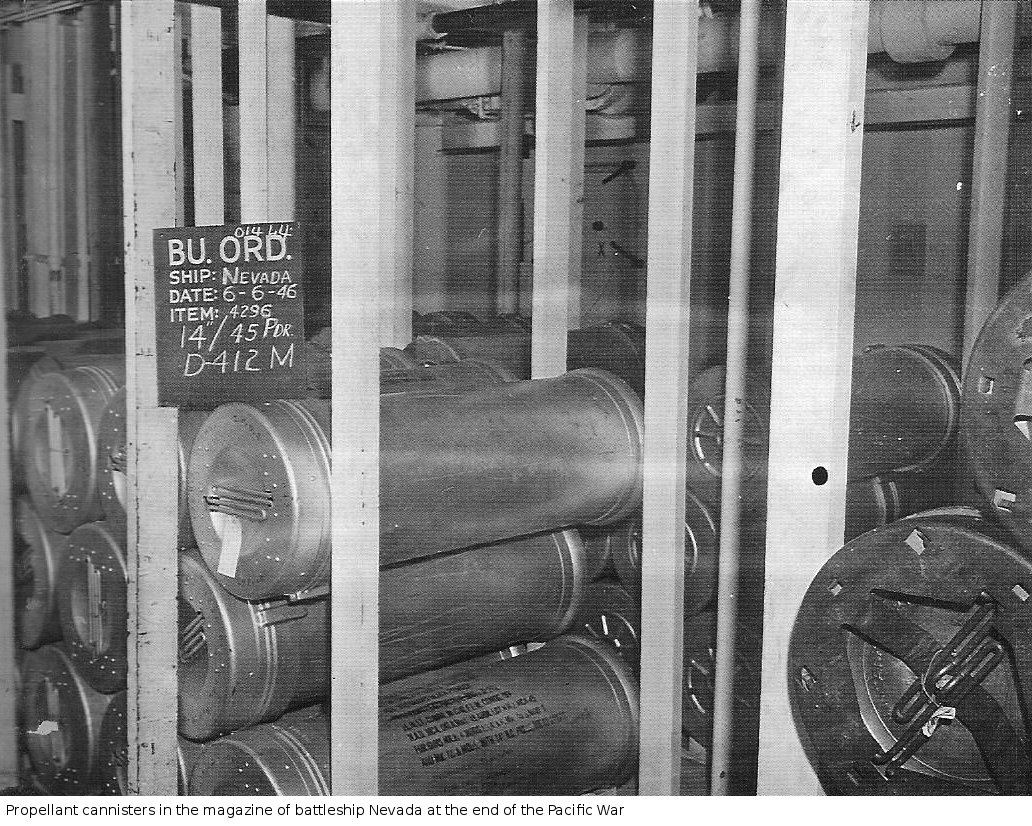
For safety reasons, the propellant bags were stored in
metal cannisters until just before they were needed. Gun crews could
reduce the muzzle velocity and
thus the range of a large naval gun by using fewer bags of propellant.
This could be advantageous for reducing barrel wear
and allowing plunging fire on ships and shore installations.
Semi-fixed ammunition has some advantages even at very large calibers and was used for even the largest guns by the German Navy. The powder cartridges are safer, being better protected against penetrating hits to the ship's magazines and having less potential for flareback accidents when the gun breech is opened for a new round. Cartridges also help to seal the breech, allowing simpler breech designs with the potential for higher rates of fire. However, this is partially negated by the heavier and more complex handling equipment required for cartridges. All the major participants in the Pacific War used bagged ammunition for their large-caliber guns.
For small automatic guns, the cartridge is typically
described by its metric caliber, which gives the bore and length of the
cartridge in millimeters plus an optional suffix. Thus, the Japanese
Type 89 Model 2 machine gun used a 7.7 x 58 SR cartridge, meaning the
cartridge fired a 7.7mm bullet, was 58mm long, and was semi-rimmed.
Other suffixes in use were R for rimmed, B for belted, and RB for
rebated rimless, all of which described the shape of the base of the
cartridge. Only fixed or semi-fixed ammunition was suitable for rapidly
firing antiaircraft guns, because bagged propellant could not be loaded
at high gun elevations. Bagged ammunition also required a more complex
(and therefore slower) breech mechanism, since there was no cartridge to help seal the breech.
The projectile itself might be one of several types. Armor piercing (AP) and high explosive (HE) shells have already been mentioned, but in addition a gun might be supplied with timed or proximity fused shells for antiaircraft use. Shells for automatic guns could carry a tracer to allow the gunners to better judge the trajectory of the shells, and the smallest caliber guns were sometimes supplied with incendiary shells or solid shot. Star shells were designed, not to inflict damage directly, but to illuminate enemy ships or positions at night.
Unless otherwise specified, the statistics for gun performance are given for AP or ball rounds.
Projectile weight. The kinetic energy of a projectile is proportional to its mass times the square of its velocity. The weight of a high explosive shell is also a rough measure of its explosive power. Ceteris paribus, a heavier projectile is more destructive. A lighter projectile generally loses its punch more quickly at longer ranges than a heavier projectile.
By the time of the Pacific War, the major naval powers
favored relatively heavy shells suitable for the anticipated long-range
gunnery duels. These lower velocity shells also produced less barrel
wear.
Velocity. This is the muzzle velocity
of the projectile fired by the gun. A faster projectile is much
more destructive, since its kinetic
energy is proportional to its mass times the square of its
velocity. Faster projectiles also have a flatter trajectory,
which is sometimes a disadvantage, and the U.S. Navy deliberately chose
a larger, slower shell for its 16" guns to increase the number and
effectiveness of plunging hits on armored decks. High-velocity guns
suffer from
greater barrel wear, degrading accuracy over time and requiring more
frequent refits. U.S. Navy practice was to reline a gun when its
remaining barrel life was equal to the ammunition loadout.
Maximum elevation. This is the maximum firing angle of the gun as typically mounted. It affects the usefulness of the gun against aircraft, and it also determines whether the gun can use plunging fire against distant targets. Plunging fire is fire that comes in at a steep angle, so that the shells strike the deck of an enemy ship rather than the sides. In general, armored ships of the Second World War had lighter horizontal than vertical armor. Plunging fire was also more effective against land fortifications than flat trajectory fire, for similar reasons. The older U.S. battleships were particularly useful for delivering plunging fire during shore bombardment.
Range. The maximum horizontal distance to which the gun can fire a projectile.
Altitude. For antiaircraft guns, this
determines the
maximum altitude its projectiles can reach.
Rate of fire. Nominal rate of fire of the gun. This varied from about two rounds a minute for battleship guns to hundreds of rounds per minute for the lightest antiaircraft weapons. The firing cycle (time to load and fire a single round) is sometimes specified instead, especially for the heavier guns. In general, the heavier the gun, the lower the rate of fire. Guns between 3" and 6" diameter were sometimes described as quick-firing guns since they could fire several rounds a minute, important when fending off destroyer attack (their original role.) Guns smaller than 3" were usually automatic weapons.
Gun power. This is provided only for automatic weapons used in aerial combat. It is a measure of the killing power of the gun in arbitrary units as calculated by Williams and Gustin (2003). It is based on the killing power of an individual round (based on its kinetic energy and any high explosive fill) times the rate of fire of the gun.
Penetration. This is provided only for naval antiship
guns. It is the number of inches of vertical armor the shell could
penetrate at the specified range.
Loadout. The typical number of rounds available for the gun when the magazines are fully loaded. This could vary considerably for the same gun on different classes of ships and at different times. For example, the "standard" allotment for 5" guns on U.S. destroyers prior to war was 100 rounds per gun, but the "mobilization" allotment was typically 300 rounds per gun. This proved inadequate, and by the time the war ended, the allotment was approaching 600 rounds per gun. The older American battleships had storage for 100 rounds per gun, but this was substantially increased for the battleships designed in the 1930s.
40mm/40
Mark
VIII antiaircraft gun
4"/45
Mark XVI dual-purpose gun
20mm
Oerlikon antiaircraft gun
References
Frank (1990)
Friedman (1985, 2006, 2008)
Garzke
and Dullin (1985)
NAVPERS 16116A (1946-3; accesssed 2013-7-15)
Rivers (1998; accessed 2013-9-21)
The Pacific War Online Encyclopedia © 2006-2007, 2009, 2012, 2014-2015 by Kent G. Budge. Index